中文简体
中文简体Understanding Gear Motors and Why Torque Is the Central Selection Criterion
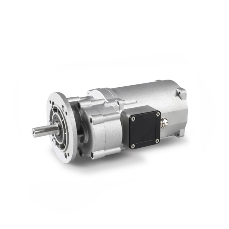
A gear motor combines an electric motor with a gearbox into a single integrated unit, using gear reduction to convert the motor's high-speed, low-torque output into a lower-speed, higher-torque output suitable for driving mechanical loads. The gear ratio determines how much the output speed is reduced and, correspondingly, how much the output torque is multiplied relative to the motor's base torque. For applications involving heavy loads, slow movements, or sustained force — conveyor systems, industrial mixers, rotary actuators, lifting equipment, and automated gates — selecting a gear motor with sufficient torque output is the single most consequential decision in the specification process. Undersizing torque leads to motor overheating, premature gearbox wear, and eventual failure. Oversizing adds unnecessary cost, weight, and energy consumption.
High-torque gear motors are specifically those where the application demands output torque well above what the base motor could deliver without gear reduction. They are found across industrial automation, material handling, agricultural machinery, construction equipment, and robotics. The selection process for these units requires a systematic approach — calculating load torque, applying safety factors, matching gear ratio to speed requirements, and validating the chosen unit against thermal and mechanical service conditions.
Step 1 — Calculate the Required Output Torque
The starting point for any gear motor selection is an accurate calculation of the torque that the output shaft must deliver to move the load. This is called the load torque, and it must account for every resistive force the motor has to overcome — not just the static weight of the load, but also friction in bearings and guides, acceleration inertia during startup, and any process-specific forces such as cutting resistance or mixing viscosity.
For a rotating load, torque is calculated as force multiplied by the radius at which the force is applied (T = F × r). For a linear load driven through a lead screw or rack-and-pinion, the linear force must be converted to rotary torque using the mechanical advantage of the transmission. In lifting applications, the torque required at the drum or sprocket equals the load weight multiplied by the drum radius, divided by the transmission efficiency. Always calculate for the worst-case load condition — typically at startup when static friction is highest and acceleration demand peaks simultaneously.
Once the raw load torque is established, apply a service factor. The service factor accounts for shock loading, duty cycle, and operating environment. Smooth, continuous loads use a service factor of 1.0 to 1.25. Moderate shock loads — such as conveyors with uneven product flow — use 1.25 to 1.75. Heavy shock applications, including crushers, reciprocating compressors, and heavy-duty agitators, require service factors of 1.75 to 2.5 or higher. The required gear motor output torque equals the calculated load torque multiplied by the service factor.
Step 2 — Determine the Required Output Speed and Gear Ratio
Gear ratio selection is directly linked to the speed at which the output shaft must rotate. Standard induction motors run at synchronous speeds of 1,500 RPM (4-pole, 50 Hz) or 1,800 RPM (4-pole, 60 Hz) before slip. The required gear ratio is the motor base speed divided by the required output speed. A conveyor that needs its drive sprocket to turn at 30 RPM, paired with a 1,500 RPM motor, requires a gear ratio of 50:1.
Higher gear ratios produce higher output torque for a given motor power, which is why high-torque applications frequently specify large gear reductions. However, very high gear ratios — above 100:1 in a single-stage gearbox — are mechanically inefficient and physically impractical. Most manufacturers achieve ratios above 50:1 through multi-stage gearboxes, where two or three gear stages are stacked in series. Each stage introduces efficiency losses, typically 3–5% per stage, so a three-stage gearbox may have an overall efficiency of 85–92%. This efficiency loss must be factored back into the motor power requirement: required motor power equals output power divided by gearbox efficiency.
Gear Motor Types and Which Applications Each Suits Best
| Gear Motor Type | Typical Gear Ratio Range | Efficiency | Best Applications |
| Helical Gear Motor | 3:1 – 200:1 | 95–98% | Conveyors, mixers, compressors |
| Worm Gear Motor | 5:1 – 100:1 | 50–90% | Gates, lifts, low-speed drives with self-locking |
| Planetary Gear Motor | 3:1 – 10,000:1 | 90–97% | Robotics, heavy lifting, precision actuators |
| Bevel Gear Motor | 3:1 – 60:1 | 93–97% | Right-angle drives, agitators, packaging |
| Cycloidal Gear Motor | 10:1 – 300:1 | 92–95% | High-shock loads, crane drives, heavy industry |
Helical gear motors are the default choice for most industrial applications because of their high efficiency, quiet operation, and wide availability. Worm gear motors sacrifice efficiency — particularly at high gear ratios where worm efficiency can drop below 60% — but offer inherent self-locking behavior that prevents back-driving under load, making them well-suited to gate operators and vertical conveyors where the load must be held stationary when the motor is off. Planetary gear motors deliver the best torque density of any type, meaning the highest torque output for a given physical size, which is why they dominate robotics, servo actuator, and aerospace applications where space and weight are constrained.
Step 3 — Select the Motor Type and Power Rating
The motor integrated into the gear motor determines the unit's control characteristics, power supply compatibility, and suitability for variable-speed operation. AC induction motors are the most common choice in fixed-speed industrial applications due to their simplicity, low cost, and robustness. When paired with a variable frequency drive (VFD), an AC motor gear unit can operate across a range of speeds while maintaining good torque characteristics down to roughly 10–20% of base speed. Below this range, the motor's self-cooling fan becomes ineffective, requiring a separately powered cooling fan or a motor with a higher service class rating.
DC motors offer simpler speed control without a VFD but require more maintenance due to brush wear and are less suited to harsh environments. Brushless DC (BLDC) motors and permanent magnet synchronous motors (PMSM) are increasingly used in high-performance gear motor applications because they offer precise speed and torque control across a wide range, high power density, and minimal maintenance. These are the motor types most commonly found in modern automated guided vehicles (AGVs), collaborative robots, and high-precision industrial machinery.
Required motor power is calculated from the output power demand: motor power (W) equals output torque (Nm) multiplied by output angular velocity (rad/s), divided by gearbox efficiency. Always select a motor with a continuous power rating that meets or exceeds this calculated value at the specified duty cycle. If the application involves frequent starts, plugging, or dynamic braking — all of which generate thermal stress beyond what steady-state power calculations capture — consult the motor manufacturer's derating curves for the specific duty cycle class.
Critical Specification Parameters to Verify Before Finalizing Selection
- Output shaft radial and axial load capacity: The gearbox output shaft must be rated to handle not just the transmitted torque but also the radial force from sprockets, pulleys, or cams mounted directly on it. Exceeding the shaft's radial load rating causes bearing failure long before the torque rating is reached.
- Thermal rating and duty cycle: Every gear motor has a thermal power limit — the maximum continuous power it can dissipate without exceeding safe operating temperature. For intermittent duty applications (S2, S3, S4 duty classes), the permissible torque may be substantially higher than the continuous S1 rating. Verify which duty class applies to your application before comparing units.
- Mounting configuration: Gear motors are available in foot-mount, flange-mount, shaft-mount, and torque-arm configurations. The mounting style affects how reaction torque is handled and whether the unit can accommodate the misalignment that occurs in real installations. Shaft-mount designs that clamp directly onto the driven shaft eliminate the need for a separate coupling but require the gearbox housing to be restrained by a torque arm.
- IP (Ingress Protection) rating: Applications in wash-down environments, outdoor installations, or dusty industrial settings require an IP65 or higher rating. Standard industrial gear motors are often IP55 as supplied; confirm that the shaft seal specification also meets the IP rating under the operating conditions, as seal failure is the most common source of IP rating degradation in service.
- Lubrication type and re-lubrication interval: Sealed-for-life gear motors filled with synthetic lubricant simplify maintenance and are preferred for hard-to-access installations. Units requiring periodic oil changes must be accessible, and the re-lubrication interval must be compatible with the facility's planned maintenance schedule to prevent premature gear and bearing wear from lubricant degradation.
- Noise level: Worm gear motors tend to run louder than helical units at equivalent power levels. If the gear motor is installed in a noise-sensitive environment — food processing facilities, laboratories, or proximity to occupied spaces — specify a helical or planetary unit and verify the manufacturer's noise data at the rated operating point.
Common Mistakes That Lead to Premature Gear Motor Failure
Even correctly sized gear motors fail prematurely when installation or operational practices introduce stress conditions the specification didn't account for. One of the most common errors is applying excessive overhung load — mounting a heavy sprocket or pulley too far from the gearbox bearing, which multiplies the bending moment on the output shaft beyond its rated capacity. Always mount driven components as close to the gearbox housing as possible and verify the overhung load against the manufacturer's load chart at the specific shaft position.
Thermal management errors are equally damaging. Installing a gear motor in an enclosed cabinet without adequate ventilation, positioning it where it receives radiant heat from nearby furnaces or ovens, or operating it at a duty cycle above the S1 continuous rating without derating all result in sustained overtemperature that degrades lubricant and accelerates bearing wear. If the application cannot avoid high ambient temperatures, select a unit rated for elevated temperature operation or add forced cooling.
Finally, neglecting the startup torque requirement is a consistent cause of undersizing. Many applications require a starting torque significantly higher than the running torque — conveyor systems with heavy static loads, mixers starting under full product load, and gate operators that must overcome static friction after long rest periods can all demand two to three times the steady-state running torque for the first few seconds of operation. If the gear motor is selected purely on running torque, its gearbox and motor may be within specification during steady-state but repeatedly stressed at startup, causing cumulative damage that shortens service life well below expectations.